Guomao Group has been a manufacturer specializing in power transmission industry for 30 years with a wide product series including speed reducer boxes, gear motors, electric motors and become a bellwether in the intelligent automation.
Wide Range of Fields
We have established business relationship with leaders in various fields such as energy, mining, construction, logistics, pharmaceuticals, chemicals, machinery and robotics.
Wide Range of Applications
Our products are widely used in Garment Shops, Manufacturing Plant, Machinery Repair Shops, Food & Beverage Factory, Printing Shops, Construction works, Energy & Mining, Food & Beverage Shops, Hotels, Building Material Shops, Farms, Restaurant, Home Use, Retail, Food Shop, Advertising Company, Energy & Mining, Other.
Quality Assurance
Each batch of goods has a corresponding quality inspection report to solve your concerns about product quality.
Quick Transportation
We cooperate with professional sea, air and logistics companies to provide you with the best transportation solution.
What Is Geared Motor
A geared motor is a component whose mechanism adjusts the speed of the motor, leading them to operate at a certain speed. geared motor have the ability to deliver high torque at low speeds, as the gearhead functions as a torque multiplier and can allow small motors to generate higher speeds. If you want to know the specifications and prices of Geared Motor, please contact us!
Savings on Expenses
Using a gear motor to increase torque and lower speed eliminates the expense of running the system. The effectiveness and dependability of gear motors provide instant benefits to an application. Several gear motors are inexpensive and easy to install and need little maintenance, resulting in reduced unplanned downtime to replace the gears.
Reduced Speed
Gearheads are sometimes known as "speed reducers." Gear ratios are also known as "speed reduction ratios" at times. Whilst speed controllers now handle speed reduction, gearheads were formerly employed to lower the speed of a motor. When using a geared motor, the speed of the motor is split by the gear ratio. An 1800 RPM AC synchronous motor with a 5:1 gearhead, for instance, will operate at 360 RPM.
Environmental Advantage
Reliable speed reducers can save a lot of money on energy and motor components. Furthermore, gear motors benefit both the environment and the employees who use them. Commercial electric motor systems account for around one-twelfth of total greenhouse gas emissions from fossil-fuel energy plants. The generation of greenhouse gases may be greatly decreased by lowering motor power usage with effective speed reducers, such as gear motors.
Torque
When directly connected to the motor axle, gear motors offer an advantage. This results in a mechanical advantage depending on the ratio of the number of gears to the number of teeth on every gear. For instance, if a motor produces 100 lb-in. of torque, adding a 5:1 gearhead produces 500 lb-in. of output torque.
Increased Rigidity
Geared motors are more robust and resilient to torsional stresses. As a result, as compared to conventional motors, geared motors are less prone to problems generated by load torque variations. Even though the load fluctuates, high stability and position precision may be expected. For instance, higher gear tension in a geared motor gives more holding torque, allowing a surveillance camera to remain in place even in high gusts.
Improved Damping Characteristics
If the inertial load is large or acceleration/decleration rate is high, a geared motor can increase damping effects more effectively. This ensures more stable operation compared to an ungeared motor; especially during starting and stopping. Geared motors are ideal for applications where a large inertial load, such as an index table, must be driven.
Shorter Positioning Time
For large inertial loads, the use of a geared motor will achieve a shorter positioning time than a standard type motor. In the graphs below, we compare the fastest positioning time between an ungeared closed-loop stepper motor and a geared closed-loop stepper motorat 5:1 inertia ratio and 30:1 inertia ratio.
As you can see, at 5:1 inertia ratio, the geared motor takes longer than the standard type. However, at 30:1 inertia ratio, the geared motor can position faster until a certain point (540°).
Drive Large Inertial Loads
When a geared stepper motor or servo motor is used, the inertial load that can be rotated increases by the square of the gear ratio in comparison with an ungeared motor of the same size. Bascially, you can drive an exponentially bigger inertial load with geared motors.
When using different types of motors, pay attention to how the inertial load is treated. We show some examples below.
For AC motors, we follow this formula below. When gear ratios are less than 3:1~50:1, we multiply the rotor inertia by the gear ratio squared. For gear ratios of 60:1 or higher, we only multiply the rotor inertia by 2500 as there is a limit.
Types of Geared Motor


Spur Gears
Spur gears, the most frequent form of gear used, are made with straight teeth cut or placed perpendicular to the shaft of the gear on a spherical (i.e., cylindrical) gear body. These gears use the parallel axes arrangement to transfer motion and force when joined in pairs. They can be coupled with a different spur gear, an internal gear (e.g. in planetary gear) or a gear rack (such as in a rack and pinion gear pair) depending on the application.
This sort of gear is utilized in a broad range of mechanical applications, including clocks, pumps, irrigation systems, power station machinery, material handling equipment, and clothes washing and drying machinery. Several spur gears can be utilized in a gear train to offer higher gear reduction if required for an application.
Bevel Gears
Bevel gear sets feature crossing axes that are frequently but not always perpendicular. They mate by using teeth with angled edges. Straight or spiral teeth are both possible. Straight bevel gear teeth are utilized in low-speed applications, whereas spiral teeth are employed in high-speed and performance applications.
Worm Gears
Worm gear sets are made up of a worm wheel (usually a cylindrical gear) and a worm (a screw-shaped gear). These gears are being used to transfer motion and power across shafts that are not parallel and do not intersect. They have huge gear ratios and the ability to reduce speed significantly while remaining quiet and smooth.
One contrast between worm gear pairs would be that the worm can spin the worm wheel, however, the worm wheel might not be able to turn the worm based on the direction of the worm. This feature is used in equipment that requires self-locking mechanisms.
Planetary Gear Motors
Planetary gear motors are a type of gear motor that utilizes a system of gears known as planetary gears. These gears consist of an outer ring gear, multiple inner sun gears, and planet gears that rotate around the sun gear. This arrangement results in compact and efficient power transmission.
Linear Gear Motors
Linear Gear Motors are a type of gear motor that converts rotational motion into linear motion. They are commonly used in applications where precise and controlled linear movement is required.
Hollow Shaft Gear Motors
Hollow shaft gear motors are specifically designed to have a hollow center, allowing for easy integration with other mechanical components. They are commonly used in applications where space is limited or where direct coupling to other equipment is required.
Application of Geared Motor
Manufacturing and Industrial Automation
Manufacturing and industrial automation have greatly benefited from the use of AC gear motors. These powerful machines are essential in driving various processes and machinery within manufacturing plants, increasing efficiency and productivity. AC gear motors are commonly used in conveyor systems, where they provide the necessary torque to move heavy loads efficiently along assembly lines.
Automotive Industry
One key use of AC gear motors in this sector is in power windows and seat adjustments. Another important application is in windshield wiper systems. AC gear motors play a crucial role in ensuring efficient movement of wiper blades, and under the hood for cooling fans.
Medical Devices
AC gear motors in medical devices are used in robotic surgical systems. Another area where AC gear motors are commonly found is in imaging equipment such as MRI machines and CT scanners. AC gear motors also find applications in rehabilitation equipment like motorized wheelchairs and mobility scooters. The application also extends to devices like medical pumps, diagnostic equipment, and patient care systems.
HVAC and Building Automation
In HVAC applications, AC gear motors are used for tasks such as controlling dampers, valves, and fans. Building automation goes beyond just heating and cooling; it encompasses various aspects of facility management like lighting control, security systems, access control, etc. In this context too, AC gear motors find their application. They enable the smooth operation of automated doors or gates while ensuring safety measures are met.
Know Your Application Requirements for Your Gearmotor
The first step in selecting a gearmotor is reviewing your application requirements. These include but are not limited to:
General requirements: Envelope size, mounting orientation, mounting type and size, overhung and side loads, shock load and lubrication type.
Input power source: Voltage, frequency (Hz), maximum current (Amps) and control type, if applicable.
Gearmotor specifications: Size, weight, desired noise level, life expectancy and maintenance level.
Gearmotor performance: Speed, torque, duty cycle, horsepower, starting and running torque (full load).
Operation environment: Application and ambient temperature, and ingress protection (IP) rating.
Know the Speed and Torque Requirements of The Load to Be Driven
To ensure your gearmotor is properly sized for your intended application, it's important to know your output speed, starting and running torque. Selecting the proper gearmotor is a matter of matching output speed (RPM) and torque to your application's needs. The output speed is determined by your machine's requirements and should be already known. That leaves the starting and running torque to be determined. Keep in mind, when you choose a pre-engineered gearmotor, the manufacturer has done most of the heavy lifting to ensure the motor and gearbox will work seamlessly.
Once you have calculated the starting and running torque needed, you will also need to review the gearmotor's potential design limitations, including the running (full-load) output torque, output speed, overhung load, shock load, thermal characteristics and duty cycles.
Select the proper motor
Next, use your list of application requirements and compare them to the motor specifications of the different types you are interested in such as a universal, brushless DC, AC induction or a permanent magnet DC gearmotor. Because each application has its own unique characteristics and requirements, it is important to note which factor such as horsepower, starting torque or efficiency is most important to your application. During this phase, you may decide that matching a gearbox and motor separately will best suit your needs.
Test the motor
Once you have selected a gearmotor, it is important to run several tests to ensure the motor runs well in a typical operating environment. If the motor becomes unreasonably hot, is too noisy or appears stressed, repeat the motor selection process or contact the manufacturer.
Taking the time to properly size your gearmotor will help ensure that it will last for years and operate at peak efficiency.
How to Maintain Geared Motor
Maintain Good Housekeeping
Although it may appear simple, gearboxes frequently operate in a dirty and dusty environment. While to some extent this is unavoidable, it is critical to minimise the consequences of the employment environment. Such a dirty and rusty environment could raise the gearbox's working temperature or perhaps cause it to become contaminated. As a result, industrial gearboxes should be dusted and brushed clean on a regular basis.
Conduct Regular Inspections
While a full inspection may appear to be too difficult, a simple visual inspection of gear contact patterns through an inspection port can help prevent catastrophic failures in the future. If there isn't any in-house inspection experience, an expert might be recruited to execute the examination and train people.
By overcoming problems for conducting an inspection, you can help to extend the life of your gearbox and avoid catastrophic failure. This could save time, money, worker harm, and damage to nearby equipment.
Before opening the gearbox inspection port, you should conduct a comprehensive external inspection. Use an inspection form to keep track of critical information that would otherwise be lost once the cleaning is done. Examine the exterior of the gear housing for symptoms of overheating, corrosion, contamination, oil leaks, and damage before cleaning it.
Tightening torque of structural fasteners carrying large stresses, such as torque arm bolts is to be measured and corrected Look for signs of movement at structural interfaces, such as cracked paint or fretting corrosion. Note the condition of the fasteners and look for fretting corrosion or other signs of movement on load-bearing surfaces of components, for taking corrective action.
Keep an Eye Out for Overheating
Overheating can be detected by discoloured or burned external paint, as well as dark oil in the sight glass. Using an infrared temperature gun, monitor the gearbox temperature on a regular basis and look for any rapid variations in temperature. Overheating can be detected by the following symptoms:
- Shafts, seals, and breathers all emit smoke.
- Housings with discoloured or burned paint
- Water placed on the housing or shafts immediately evaporates, boiling or crackling.
- Colors should be tempered on unpainted surfaces.
- Components made of melted plastic, such as shipping plugs
- Low levels of oil in the sight glass or on the dipstick
- In a sight glass or on a dipstick, there is a dark oil.
Foam in the sight glass
Sludge on the filter element or water in the sight glass (may indicate oil cooler failure)
Chip detectors, filters, or metal chips on magnetic plugs (may denote gear or bearing failure caused by overheating)
Look for Wear & Tear Signs
Internal gears can be inspected by removing inspection covers or using an endoscope. Look for pitting and spalling as evidence of wear (material from the surface of gear tooth flanks being removed). Using 'engineers blue,' check the contact patterns between gear teeth for misalignment, since this could indicate bearing or bearing housing wear.
Conduct Vibration Analysis
Since many gearboxes work in a noisy environment, not all changes in gearbox noise can be captured. Vibration study of the internal bearings and gears on a regular basis will identify any substantial changes in the gearbox's internal condition and help prevent any unanticipated production loss.
Check the Condition of Your Shaft
Check for any increase in backlash between the gears' mesh, as well as any increase in end play or lift at the input and output shafts, with a dial indicator. Backlash increases could be a sign of gear tooth wear, which isn't usually evident to the human eye. Increased shaft end play or lift indicates wear in the bearings' rolling elements, as well as wear in the bearing housings.
Speak to Our Specialists at Premium Transmission
Bring in the specialists who can advise you and assist you to guarantee your site's gearboxes are running to their full operational efficiency, by providing guidance or support in inspecting, maintaining and repairing, or replacing your gearbox.
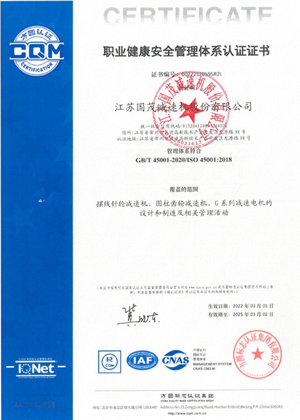
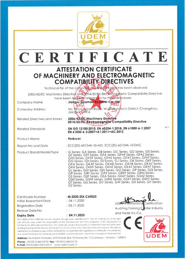
Certifications


Frequently Asked Questions
We're professional geared motor manufacturers and suppliers in China. We warmly welcome you to wholesale high quality geared motor made in China here from our factory. For customized service, contact us now.
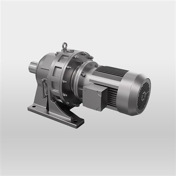
zly two stage cylindrical speed reducer gearbox, heavy duty gearbox, braking ac electric induction motor


